
After Philips came out with their Hue few years ago, we started to see many
Chinese bulbs with the same capabilities.
Usually those bulbs connect to some kind of Hub at 2.4Ghz (not wifi), and from there
the Hub is connected to the home network and we can control those bubs from the smartphone,
or you can buy a remote control that connects to the hub/directly to the bulb.
Those new Chinese bulbs are very cheap (about $10).
Another thing that came out not long ago is the the ESP8266 – a little SOC (system on a chip) that
includes WiFi and a micro controller on the same chip, and it costs about 2-3$.
A while ago I bought some modules back never got the time to play with them very much.

So I’ve been thinking- why not taking one of those cheap bulbs that has the capability to change colors,
and replace its brain with an ESP8266 and control it from the web/smartphone!
Then, I bought a Mi Light light bulb from Banggood, and started exploring it.

After a little playing and checking, you can see in the photo above my findings.
The Mi Light use a micro controller from STM to control the bulb,
a Low Power 2.4Ghz Transceiver to communicate with the hub/remote, a 3.3V voltage regulator,
and some transistors that controls the RGB and the WHITE leds (My guess: the white is MOS and the colors are BJT).
Update 10/9/2016:
There is a mix between the Green and Red colors in the picture.
Also, I made measurements for the currents of each color:
Blue: 87.6 [mA]
Red: 99.2 [mA]
Green: 71.3 [mA]
White: 158.3 [mA]
(I don’t have the hub or the remote so it was a little tricky to find which transistor controls which led,
I assumed that the first one control the white one because it different type of transistor)
After studying the Mi Light, I moved to the ESP8266.
I chose the ESP-03 module because it was small and has many GPIOs from the chop that are available.
The ESP-03 module header are not standard, and I wanted to use the 1″ header so I could pull
it form the Mi Light if I wand to update the firmware.

So apparently someone already found some nice way solder a 1″ header to this module
And this is what came out

Now I had to put it on a breadboard and start coding.
I connected some of the ESP GPIOs thru 200Ω resistors to Red, Green, Blue and White LEDs,
and used a breadboard power supply to supply 3.3V to the ESP.

I installed the “Unofficial Development Kit for Espressif ESP8266 “from here:
http://www.esp8266.com/viewtopic.php?f=9&t=820
And connected the ESP according to this (no RST in ESP-03)

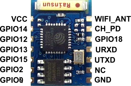
(I took it schematic from here and ESP-03 image from here)
And.. after few days of struggle with the code, I managed to something that was unstable and I was not happy with.
So I tried the Arduino core for the ESP8266: https://github.com/esp8266/Arduino
This is very easy to work with, and in a few hours of learning I had something I was happy with.
#include <ESP8266WiFi.h>
#include <WiFiClient.h>
#include <ESP8266WebServer.h>
#include <ESP8266mDNS.h>

const char *ssid = "YOUR SSID";
const char *password = "YOUR PASSWORD";

ESP8266WebServer server(80);

//Assign color to gpio
#define rgbRED 12
#define rgbGREEN 13
#define rgbBLUE 2
#define rgbWHITE 14

//RGB Struct
struct RGB {
  byte r;
  byte g;
  byte b;
  byte w;
};

RGB miColor;

//Update PWM according to the new values
void updateLights()
{
  analogWrite(rgbRED, miColor.r);
  analogWrite(rgbGREEN, miColor.g);
  analogWrite(rgbBLUE, miColor.b);
  analogWrite(rgbWHITE, miColor.w);
}

//Handle main page
void handleRoot() {
  server.send(200, "text/plain", "Hello from Mi Light!");
}

//Handle color change
void handleColorChange(){
  for (uint8_t i=0; i<server.args(); i++){
    switch (server.argName(i)[0])
    {
      case 'r':
        miColor.r = server.arg(i).toInt();
      break;
      case 'g':
        miColor.g = server.arg(i).toInt();
      break;
      case 'b':
        miColor.b = server.arg(i).toInt();
      break;
      case 'w':
        miColor.w = server.arg(i).toInt();
      break;
    }
  }
  //Update the light with to the received data
  updateLights();

  String message="Colors: \r\n";
  message += "Red: " + (String)miColor.r + "\r\n";
  message += "Green: " + (String)miColor.g + "\r\n";
  message += "Blue: " + (String)miColor.b + "\r\n";
  message += "White: " + (String)miColor.w + "\r\n";
  server.send(200, "text/plain", message);

}

void handleNotFound(){
  String message = "File Not Found\n\n";
  server.send(404, "text/plain", message);
}

void setup(void){
//Initialize starting color (only white on full power)
  miColor = (RGB){0,0,0,255};

//Initialize GPIO's as OUTPUT
  pinMode(rgbRED, OUTPUT);
  pinMode(rgbGREEN, OUTPUT);
  pinMode(rgbBLUE, OUTPUT);
  pinMode(rgbWHITE, OUTPUT);

//I use 8bit RGB color space, so we will limit the PWM to 255 (2^8)
  analogWriteRange(255);

//Set the output to their initialized state (only white is on)
  updateLights();

 //Start the serial and connect to network
  Serial.begin(115200);
  WiFi.begin(ssid, password);
  Serial.println("");

  // Wait for connection
  while (WiFi.status() != WL_CONNECTED) {
    delay(500);
    Serial.print(".");
  }
  Serial.println("");
  Serial.print("Connected to ");
  Serial.println(ssid);
  Serial.print("IP address: ");
  Serial.println(WiFi.localIP());

  if (MDNS.begin("ESP_MiLight")) {
    Serial.println("MDNS responder started");
  }

//handle root page
  server.on("/", handleRoot);

//To change the colors the esp will listen to data at http://host/rgb
  server.on("/rgb", handleColorChange);

//Handle path not found
 server.onNotFound(handleNotFound);

  server.begin();
  Serial.println("HTTP server started");
}

void loop(void){
  server.handleClient();
}
How it works:
When the micro controller is booting – first it turns the white color by default, and then I’m starting a web sever.
Then, to change color – I’m sending HTTP POST/GET request to the ESP with all the values I want.
I’m using 8-bit color space, that means that each R-G-B color can have 255 values.
This value represents the amount of that color: 0 – no color at all, 255 – maximum of that color.
If you want to generate a pink color you will have:

For the White color, I used 255 options too that represents the lighting level.
To control the amount of light of each led, the ESP generates PWM signal
that turn the light on and off very fast, and the average voltage that the LED gets is decreased
according the width of the pulse.
So If I want only pink color, I will have to send the ESP this:
http://10.0.0.44/rgb?r=255&g=204&b=229&w=0
(let’s say that for this example ESP’s IP address is 10.0.0.44)
Now that I have a working ESP, I need to take what I found about the Mi-Light and connect the ESP instead of the MCU.
So first, I cut the voltage traces that goes to the STM MCU, and to the RF transitive (at the blue lines)

Then I used 3.3V Voltage regulator that was on the board already, because the ESP takes 3.3V.
Later I found that this voltage regulator can deliver only 30mA and the ESP needs about 200-250mA max,
so I had to add one of my own, so basically you can just remove the old voltage regulator and then you don’t have to
cut the traces.
It will also help you to connect to the board power supply (16V DC) and GND from the top of the PCB (marked as VIN and GND),
and it will be neater than the way I did it (I made my connection from the back)
* You can connect to 16V power supply from the bottom-right connector (marked as 16V) too.
To run the ESP it needs less connections than before (when I programmed it):

(schematics from here)
And of course a 100uF capacitor from GND to 3V3.
I used lm1117 voltage regulator because it’s small and what I had available.
I built a little board with a 100uF capacitor, 10k resistors and the lm1117 voltage regulator (not in the photo)


This PCB gets from a regulator that inside the bulb 16V DC and this regulator should handle this.
Before connecting the new board – desolder the old Antenna, we have no use
for it now and we will have no room for the new board we made.
Then, I connected the GPIO to the transistors:
12 – RED
13 – GREEN
2 – Blue
14 – White
The red, green and blue are were connected before the 2.2k resistor (refer to the first image),
the white was connected after the 100k resistor and was connected the the gate of the transistor.


Well.. it worked and then I fried the ESP 🙁
I need to work on my soldering and practice a little more, because I had a short somewhere.
When I moved it while it was working – I created a short somewhere – and this is the end.
Now I’m waiting for a new ESP-03.
I will update when it arrives.
Next on this project:
Build a phone app to control the lights, and connect it the the phone notifications –
when I get a whatsApp message – the light will turn green etc..