
After Philips came out with their Hue few years ago, we started to see many
Chinese bulbs with the same capabilities.
Usually those bulbs connect to some kind of Hub at 2.4Ghz (not wifi), and from there
the Hub is connected to the home network and we can control those bubs from the smartphone,
or you can buy a remote control that connects to the hub/directly to the bulb.
Those new Chinese bulbs are very cheap (about $10).
Another thing that came out not long ago is the the ESP8266 – a little SOC (system on a chip) that
includes WiFi and a micro controller on the same chip, and it costs about 2-3$.
A while ago I bought some modules back never got the time to play with them very much.

So I’ve been thinking- why not taking one of those cheap bulbs that has the capability to change colors,
and replace its brain with an ESP8266 and control it from the web/smartphone!
Then, I bought a Mi Light light bulb from Banggood, and started exploring it.

After a little playing and checking, you can see in the photo above my findings.
The Mi Light use a micro controller from STM to control the bulb,
a Low Power 2.4Ghz Transceiver to communicate with the hub/remote, a 3.3V voltage regulator,
and some transistors that controls the RGB and the WHITE leds (My guess: the white is MOS and the colors are BJT).
Update 10/9/2016:
There is a mix between the Green and Red colors in the picture.
Also, I made measurements for the currents of each color:
Blue: 87.6 [mA]
Red: 99.2 [mA]
Green: 71.3 [mA]
White: 158.3 [mA]
(I don’t have the hub or the remote so it was a little tricky to find which transistor controls which led,
I assumed that the first one control the white one because it different type of transistor)
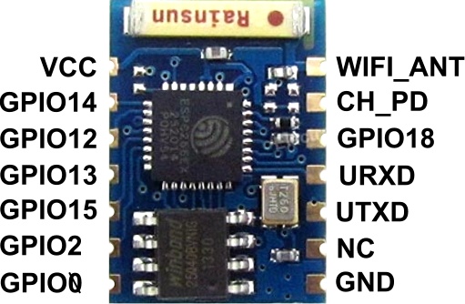
After studying the Mi Light, I moved to the ESP8266.
I chose the ESP-03 module because it was small and has many GPIOs from the chop that are available.
The ESP-03 module header are not standard, and I wanted to use the 1″ header so I could pull
it form the Mi Light if I wand to update the firmware.

So apparently someone already found some nice way solder a 1″ header to this module
And this is what came out

Now I had to put it on a breadboard and start coding.
I connected some of the ESP GPIOs thru 200Ω resistors to Red, Green, Blue and White LEDs,
and used a breadboard power supply to supply 3.3V to the ESP.

I installed the “Unofficial Development Kit for Espressif ESP8266 “from here:
http://www.esp8266.com/viewtopic.php?f=9&t=820
And connected the ESP according to this (no RST in ESP-03)

(I took it schematic from here and ESP-03 image from here)
And.. after few days of struggle with the code, I managed to something that was unstable and I was not happy with.
So I tried the Arduino core for the ESP8266: https://github.com/esp8266/Arduino
This is very easy to work with, and in a few hours of learning I had something I was happy with.
#include <ESP8266WiFi.h>
#include <WiFiClient.h>
#include <ESP8266WebServer.h>
#include <ESP8266mDNS.h>

const char *ssid = "YOUR SSID";
const char *password = "YOUR PASSWORD";

ESP8266WebServer server(80);

//Assign color to gpio
#define rgbRED 12
#define rgbGREEN 13
#define rgbBLUE 2
#define rgbWHITE 14

//RGB Struct
struct RGB {
  byte r;
  byte g;
  byte b;
  byte w;
};

RGB miColor;

//Update PWM according to the new values
void updateLights()
{
  analogWrite(rgbRED, miColor.r);
  analogWrite(rgbGREEN, miColor.g);
  analogWrite(rgbBLUE, miColor.b);
  analogWrite(rgbWHITE, miColor.w);
}

//Handle main page
void handleRoot() {
  server.send(200, "text/plain", "Hello from Mi Light!");
}

//Handle color change
void handleColorChange(){
  for (uint8_t i=0; i<server.args(); i++){
    switch (server.argName(i)[0])
    {
      case 'r':
        miColor.r = server.arg(i).toInt();
      break;
      case 'g':
        miColor.g = server.arg(i).toInt();
      break;
      case 'b':
        miColor.b = server.arg(i).toInt();
      break;
      case 'w':
        miColor.w = server.arg(i).toInt();
      break;
    }
  }
  //Update the light with to the received data
  updateLights();

  String message="Colors: \r\n";
  message += "Red: " + (String)miColor.r + "\r\n";
  message += "Green: " + (String)miColor.g + "\r\n";
  message += "Blue: " + (String)miColor.b + "\r\n";
  message += "White: " + (String)miColor.w + "\r\n";
  server.send(200, "text/plain", message);

}

void handleNotFound(){
  String message = "File Not Found\n\n";
  server.send(404, "text/plain", message);
}

void setup(void){
//Initialize starting color (only white on full power)
  miColor = (RGB){0,0,0,255};

//Initialize GPIO's as OUTPUT
  pinMode(rgbRED, OUTPUT);
  pinMode(rgbGREEN, OUTPUT);
  pinMode(rgbBLUE, OUTPUT);
  pinMode(rgbWHITE, OUTPUT);

//I use 8bit RGB color space, so we will limit the PWM to 255 (2^8)
  analogWriteRange(255);

//Set the output to their initialized state (only white is on)
  updateLights();

 //Start the serial and connect to network
  Serial.begin(115200);
  WiFi.begin(ssid, password);
  Serial.println("");

  // Wait for connection
  while (WiFi.status() != WL_CONNECTED) {
    delay(500);
    Serial.print(".");
  }
  Serial.println("");
  Serial.print("Connected to ");
  Serial.println(ssid);
  Serial.print("IP address: ");
  Serial.println(WiFi.localIP());

  if (MDNS.begin("ESP_MiLight")) {
    Serial.println("MDNS responder started");
  }

//handle root page
  server.on("/", handleRoot);

//To change the colors the esp will listen to data at http://host/rgb
  server.on("/rgb", handleColorChange);

//Handle path not found
 server.onNotFound(handleNotFound);

  server.begin();
  Serial.println("HTTP server started");
}

void loop(void){
  server.handleClient();
}
How it works:
When the micro controller is booting – first it turns the white color by default, and then I’m starting a web sever.
Then, to change color – I’m sending HTTP POST/GET request to the ESP with all the values I want.
I’m using 8-bit color space, that means that each R-G-B color can have 255 values.
This value represents the amount of that color: 0 – no color at all, 255 – maximum of that color.
If you want to generate a pink color you will have:

For the White color, I used 255 options too that represents the lighting level.
To control the amount of light of each led, the ESP generates PWM signal
that turn the light on and off very fast, and the average voltage that the LED gets is decreased
according the width of the pulse.
So If I want only pink color, I will have to send the ESP this:
http://10.0.0.44/rgb?r=255&g=204&b=229&w=0
(let’s say that for this example ESP’s IP address is 10.0.0.44)
Now that I have a working ESP, I need to take what I found about the Mi-Light and connect the ESP instead of the MCU.
So first, I cut the voltage traces that goes to the STM MCU, and to the RF transitive (at the blue lines)

Then I used 3.3V Voltage regulator that was on the board already, because the ESP takes 3.3V.
Later I found that this voltage regulator can deliver only 30mA and the ESP needs about 200-250mA max,
so I had to add one of my own, so basically you can just remove the old voltage regulator and then you don’t have to
cut the traces.
It will also help you to connect to the board power supply (16V DC) and GND from the top of the PCB (marked as VIN and GND),
and it will be neater than the way I did it (I made my connection from the back)
* You can connect to 16V power supply from the bottom-right connector (marked as 16V) too.
To run the ESP it needs less connections than before (when I programmed it):

(schematics from here)
And of course a 100uF capacitor from GND to 3V3.
I used lm1117 voltage regulator because it’s small and what I had available.
I built a little board with a 100uF capacitor, 10k resistors and the lm1117 voltage regulator (not in the photo)


This PCB gets from a regulator that inside the bulb 16V DC and this regulator should handle this.
Before connecting the new board – desolder the old Antenna, we have no use
for it now and we will have no room for the new board we made.
Then, I connected the GPIO to the transistors:
12 – RED
13 – GREEN
2 – Blue
14 – White
The red, green and blue are were connected before the 2.2k resistor (refer to the first image),
the white was connected after the 100k resistor and was connected the the gate of the transistor.


Well.. it worked and then I fried the ESP 🙁
I need to work on my soldering and practice a little more, because I had a short somewhere.
When I moved it while it was working – I created a short somewhere – and this is the end.
Now I’m waiting for a new ESP-03.
I will update when it arrives.
Next on this project:
Build a phone app to control the lights, and connect it the the phone notifications –
when I get a whatsApp message – the light will turn green etc..
Hello.
I have the milight old wifi box.
I can’t change any color (RGB Strip).
I can access to milight wifi box ,I can see only upgrade.
I use iPhone app ,milight.
How can I upgrade the wifi box?
Thanks…
Hey Itay! Just wanted to let you know I’ve used some of your findings as a basis for my own project where I want to reprogram the onboard STM8 chip. So thanks for posting the details on the board!
My project can be found on Hackaday: https://hackaday.io/project/8758-hacking-the-milight-wireless-bulbs
Oh also, the three color transistors are definitely NPN BJTs, I was able to measure their diode junctions. And the white one is probably an N-channel MOS as you said.
I’m happy to hear that my findings could help!
Thank you for letting me know.
Hi Itay,
I really like this idea!
i’ve been using the milight bulbs a while and am getting a bit sick by the control over them.
Sometimes it does switch on other times it doesn’t ect.
But if i read you post correctly:
wouldn’t it be possible to completly replace the control board by a esp?
The only things you currently use are the voltage regulator (which isn’t strong enough)
And then only the transistors.
so am i correct to assume that those are the only extra parts necessary?
because then completely replacing the board will be easier i think. And you will have more room!
Yes you are correct.
At first I wanted to use the Mi’s regulator and just solder the esp.
The Best will be to make a new little pcb with smd components and connection for the esp.
The only bad thing I can think about this idea is that the LED generats many heat.
Placing the new pcb with the esp on it instead of the older board, might make the esp get very hot, and its limits is something that need to be checked.
i don’t think heat will be the issue:
http://bbs.espressif.com/viewtopic.php?t=137
chip’s operating temp is from -40 to 125 degree.
http://bbs.espressif.com/viewtopic.php?t=137
Authometion.com has made such a pcb. For now it is a complete kit, but they are planning to sell the controller alone.
I have ordered a ESP-03 to test this out but removing these SMD components and soldering them on to a board that isn’t made for SMD components seems pretty hard. Have you figured out what resistors and transistors there is? That way it would be pretty simple to buy a set of resistors and transistors that are easier to mount.
The transistors for the rgb leds are NPN BJTs.
The base resistors are 2.2k ohm.
The transistor for the white led is a NMOS.
The gate resistor is 100K ohm.
Any idea on what minimum current the NPN BJTs and the NMOS should be?
Will BC337-25 transistors do for both rgb and white led?
I just made some measurements to answer you question:
LED currents:
Blue: 87.6 [mA]
Red: 99.2 [mA]
Green: 71.3 [mA]
White: 158.3 [mA]
I’m not sure if the BC337 could handle the the Power because the supply voltage of the LED’s is 16[V]
Hi Itay. Thank you for this post. It is one of the most clearly explained blogs that I have found using the ESP8266.
Have you ever heard about http://authometion.com ?
First time I hear about it.
Why buy when you can make your own, and it even much cheaper 🙂
Hi, two of your links are broken, I think I have found the equivalent links
https://github.com/esp8266/Arduino/blob/esp8266/hardware/esp8266com/esp8266/doc/boards.md
is now
https://github.com/esp8266/Arduino/blob/master/doc/boards.md
https://raw.githubusercontent.com/Links2004/Arduino/esp8266/docs/ESP_min.png
is now
https://github.com/Links2004/Arduino/blob/d0315a33e8f0d3d0e854d851e1fecb3b900ba3d3/docs/ESP_min.png
Thank You!
I fixed it.
Hi there,
What’s the lastest new on this? Did you ever try to finish this project? I do have a few milight lights and I’m fairly unhappy with the bridge and 2.4GHz signal control best would be to add the ESP8266 and implement MQTT for home automation system this should also give the ability to have states change on the apps if they’re altered by other means switch etc.
would be very interested in getting something together here?
Hi Itay,
Thanks for providing your findings. I currently try to generate a list with all bulbs/strips that can be converted to ESP8266 management and i was not sure if is worth to order some Mi Lights.
BTW, after 3 months of hard work i decide to publish my project that allow everyone cu build a complete Philips Hue system with any ESP8266 light/strip. Code: https://github.com/mariusmotea/diyHue
I manage to convert MiLight RGB-CCT version with an ESP-12S without extra power regulator, i just add an 47uF capacitor. For white leds are used MOSFET transistors, for this reason the GPIO output pins must be connected directly to gate, the other end of resistors being connected to ground. For colored leds are used NPN transistors, so the GPIO output pins must not be connected directly to base but via the resistors.
Picture here:
https://github.com/mariusmotea/diyHue/blob/master/Images/MiLight_RGB_CCT_converted_to_ESP-12S.jpg?raw=true
Hi there,
i want to reproduce your project, before i start with it, i have a few question, it will be great if you are able to help me.
1: I dont want to hardcode the Wifi info like SSID and PW … does this scratch has a smartconfig like Sonoff-Tasmota does?
2: if not, can i use Sonoff-Tasmota to get it work? using a separted setup button?
Thank you in advance.
Rajeeth
Hello,
If you don’t want to store the wifi credentials, you need to do some changes.
You can use a library like Wifi Manager if you don’t want to write it by yourself.
Tasmota might be possible as well, need to check how easy it is to control gpios with it.
If I was doing this project today, I don’t think esp-03 is the best option. yes, it’s small, but it’s hard to flash.
Wemos d1 mini is the way to go I think (need to check if it fits inside first).
Hi,
Thank you eveyone who is sharing their knowledge, specially Itay ….
Regarding to Tasmota: i used to flash sonoff products, but in that case sonoffs has button to switch to use as a access point. (MiLight doesnt have any buttons, how should that work, did you try to flash it with tasmota?)
I’ll go for Wemos d1, try with it and share the info here …
Thank you again.
Rajeeth
hey itaysp.
I read your post like years ago and was interested in it because of the same problem with these bulbs.
as I have build my own prototype (custom PCB working great hardware wise) I want to ask you one question:
How could you have used the LM1117 (I have a couple of these here) because the LEDS are driven by the supply that gives 16V and the LM1117 is only rated at 12V.
I made it using a step down converter but using a LM1117 would be nice.
Hey,
The LM1117-3.3 has max input of 20V, so theoretically, 16V should be enough.
However, when I wrote this back then, I didn’t calculate the Junction Temperatur.
Because this is a linear regulator, all the voltage difference is converted to heat, and the SOT version of the LM1117 will get very hot and eventually burn.
Pd = [ (16V – 3.3V) * 100mA ] = 1.27W
Ta = 30 C ( Ambient temperature )
Tj_max = 125 C
R_theta_ja = 61.6 C/W (SOT-223 package)
Tj = (Pd * R_theta_ja )+ Ta
Tj = (1.27 * 61.6) + 30 = 108.232 C
This is too close to Tj_max and I assumed that the ESP is drawing 100mA on average and ambient temperature of 30 C.
if you take the LM1117 in TO-220 package, the R_theta_ja is 23.8 and then is should be possible:
Tj = (1.27 * 23.8) + 30 = 60.226 C
You can read and learn more about these calculations here:
http://www.cypress.com/file/38656/download
If a small switching regulator can fit in (like all those based on MP1584), it would be a better choice.
Yeah – this is what I thought!
and the I_av of an ESP8266 is about 137mA as I remember… So its more like 1,74W..
And ambient Temp is not 30°C in this bulb when LEDs are on.
Its about 45°C (roughly guess).
Thanks for your reply.
If you want to follow my journey than have a look at this:
https://github.com/xoseperez/espurna/issues/1058